22" f/4.0 lowrider
building the telescope
| home | introduction | telescope | primary mirror | secondary mirror | eq platform |
|
22" f/4.0 lowrider
building the telescope |
|
More about planning and making of big Dobs is on these pages.
|
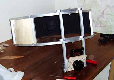
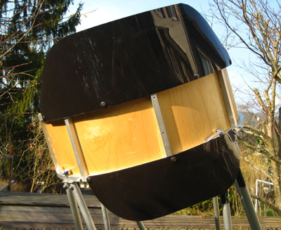
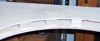
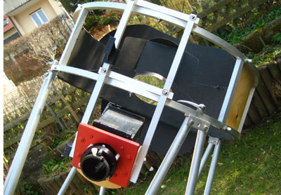
The secondary cage The secondary cage is made of 15 x15 x 1 mm square aluminum tubing, which was bent to rings as described by Jan van Gastel, using a (sufficiently stable) vice and templates made of plywood. This works quite well, but one has to take care that the rings remain planar and do not get distorted. The inner diameter of the rings is 620 mm. The rings were assembled to a cage using the same tubing with small hardwood inserts glued into the ends, and the sides of the finished cage were then lined with 1.5mm plywood. More about the making of such a secondary cage is here. The complete cage (including focuser, spider, and secondary holder, but without secondary mirror, finder, or eyepiece) weighs 2800 g. The 6 inch secondary mirror weighs 800 g, and the two finder scopes and the eyepiece add another 800 g. |
|
|
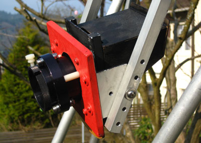
The focuser ...
is a helical Crayford HC2 made by KineOptics.
It's fantastic, both regarding weight and handling. Simply perfect
The focuser board can be rotated in two axes, such that the focuser can be precisely adjusted to the secondary. Between focuser and secondary is a filter slide which is extremely useful if you own more than one filter. Simply move the slide ... click...click...click... and you can switch between OIII, UHC and Hb, without taking out the eyepiece. Behind the filter slide is a system of two focuser baffles, as well as another half-baffle. These baffles efficiently prevent stray light from entering the eyepiece. This is a major issue for a Lowrider as the eyepiece is tilted toward the sky. These baffles allow to considerably reduce the size of the baffles around the secondary cage, which also minimizes wind resistance (see below). |
|
|
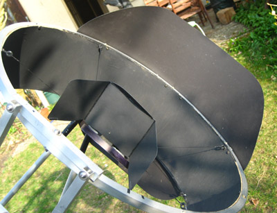
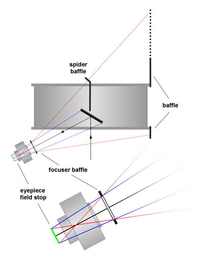
Secondary cage and focuser baffles Due to the focuser pointing toward the sky, efficient prevention of direct stray light entering the eyepiece is of particular importance for a lowrider. This is achieved by baffles at the secondary cage, opposite of the focuser. The size of these baffles can be considerably reduced by a suitable placed focuser baffle between the focuser and the secondary. Baffling becomes easier, the larger the distance of the focuser baffle from the eyepiece field stop. The inner diameter of the focuser baffle should be large enough to avoid vignetting, i.e. the complete secondary should be visible from any point within the field stop (corresponding to the blue rays). The size of the secondary cage baffles should in turn be large enough, such that its rim is not visible from any point within the field stop (corresponding to the red rays). Alternatively or additionally, a baffle may be placed on the spider above the secondary mirror, as on Dan Gray's Lowrider (here and here) or that of Roland Hermann. This allows to substantially reduce the size of the secondary cage baffle or to use a larger tilt angle a, such that the eyepiece position can be further lowered.
|
|
|
Here
is a comparison between the size of the secondary baffles without a spider
baffle (upper) and after optimization with a spider baffle (lower)
In particular with larger Dobsonians, the sensitivity to wind may become an issue, which can be reduced by decreasing the wind exposed areas. The
secondary baffles are made of by 0.6 mm PE material, which is used for
making greenhouses (Tipp by Tobias
Schöller). This material is painted flat black from the inside and
looks really good from the other side
|
|
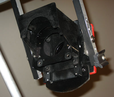
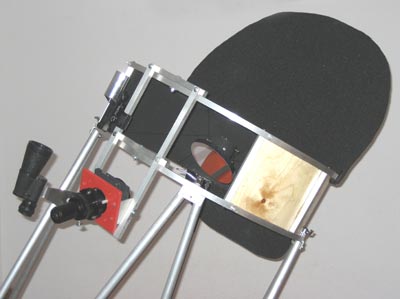
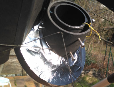
| Here is a picture of the entire baffling system, consisting of focuser baffle, spider baffle, and secondary baffles, which are optimized in respect to each other. |
|
|
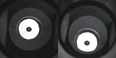
Looking through the focuser drawtube either straight (left) or as tilted as possible, except for the secondary and the reflection of the primary only dark surfaces of the telescope or the baffles are visible. Perfect! |
 |
|
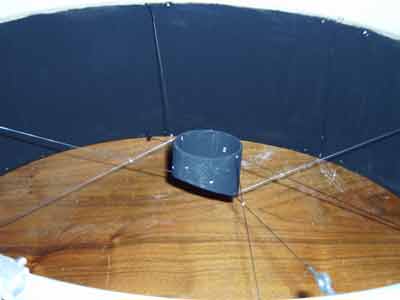
The spider ... is made of 0.8 steel wire and appears to be sufficiently stable even for such a monster secondary. The spider is mounted excentrically, which substantially reduces torsional motion of the secondary. The spider wire pairs are crossed once and fixed at the crossings to further increase the stability. For assembly of the spider, the secondary holder and the cage were fixed on a board. Otherwise, the assembly would be a mess ... A tutorial about making a wire spider is here. A |
|
|
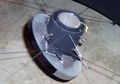
The secondary holder ... is made similarly as that of my 14" Dob, but larger. The diameters of the aluminum tubes are 70 and 50 mm, the base plate is 3 mm thick. The holder is adjustable by means of M4 machine screws and is secured by a thin rope, in case the holder should drop out of the outer tube during collimation. |
 |
|
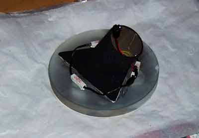
The secondary mirror (see here) is round with 150 mm diameter and 15 mm thickness. Its weight of 800 g requires a very stable secondary cage and spider. In particular, the secondary holder has a very low profile, such that the torque exerted by the secondary is minimized. The secondary is attached to the base plate of the holder by silicone glue and can be heated by a 1 W heating consisting of three 3 Ohm resistors and a power supply of 2 AAA batteries. As the secondary has quite a huge heat capacity, I wondered whether such a heater is necessary. It is! I have used this heating already several times within the first six month after first light of the telescope. The heating power of 1 Watt is just right.
|
|
| Bare metal surfaces radiate hardly in
the infrared. Radiative cooling of the secondary mirror below
ambient temperature
and in particular under the dew point can therefore be
largely reduced by covering the exposed rear side of the secondary with aluminum
tape. Thermal equilibration of the secondary to ambient temperature is still
maintained by the surrounding air. This passive means against radiative cooling considerably helps to reduce the necessity of actively heating the secondary mirror. In fact, I haven't been forced to used the active heating system after installing this passive protection on my 22" Dob's secondary. |
 |
|
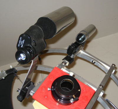
The finder scopes ... are a Baader Skysurfer red dot finder and a half of 10x50 binoculars. I prefer the upright image of this finder over the inverted image of conventional finders. |
|
|
In the meantime, I have an 80 mm finder with Amici prism and an upright image. The finder is great, the eyepiece accepts filter and makes a great little scope for extended objects such as Barnard's loop or the California Nebula. Still, I find it difficult to correlate the image in the finder with its orientation in the sky and the movements of the Dob. |
|
|
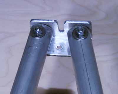
The truss poles and the clamps The original poles were made of 22x 1.2 mm aluminum tubing (as shown in the pictures). This was sufficient regarding the handling of the Dob. During windy nights, however, the observing suffered a bit from vibrations, in particular when using higher magnifications. I therefore replaced the poles with 32 x 1 mm aluminum tubing, which made the Dob again a bit stiffer. For now, I can't tell about improvements regarding vibrations as I will need to test this in the long term. The poles are connected pair wise by rectangular aluminum profiles and are attached to the secondary cage by bicycle clamps. I really like this design. It is fast, easy to use, and holds collimation . |
|
|
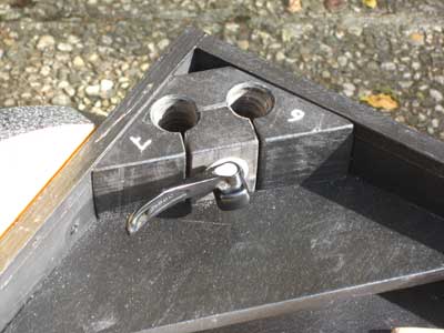
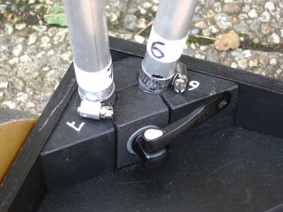
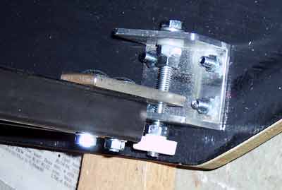
The lower clamps are in the inner corners and use as well bicycle clamps. The poles have hose clips as stoppers, such that the position of the focal plane can be precisely adjusted.
More about making the blocks is here. |
|
|
The mirror box ... is made of 12 mm plywood, screwed and glued. The box is stabilized by several reinforcements in the corners and also behind the mirror. Such elements are essential for a solid mirror box. All the plywood was treated with wood oil and several layers of wood wax. The inside of the box is painted flat black. |
|
|
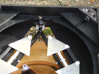
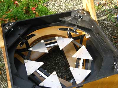
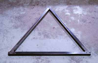
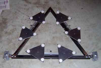
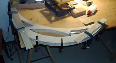
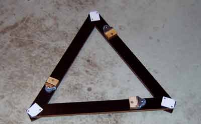
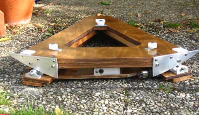
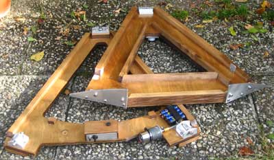
The mirror cell ... is designed as a triangle and is adjustable as a whole. This avoids movement of the mirror within its cell during collimation. Ulli Vedder found a nice way to mount the cell in the mirror box, which is very stiff and still allows precise collimation.
|
|
| The cell is made of 20 x 20 mm welded steel (thanks to Johannes and Patrick!) |
|
|
The triangles are made of 3 mm aluminum and are supported by 15 x 15 x 1 mm square aluminum tubing. |
|
|
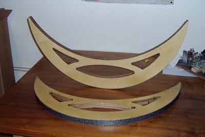
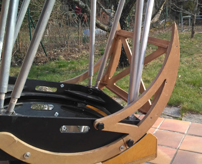
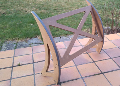
The altitude bearings ... have a diameter of 770 mm and a thickness of 30 mm. They are made of two 15 mm halves and are hollow. They are further stabilized with diagonal struts to the mirror box. As bearing material I use Ebony Star laminate. Initially, I had used coarsely structured aluminum sheet, which tended to make the movements a bit sticky. |
|
|
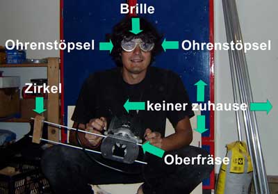
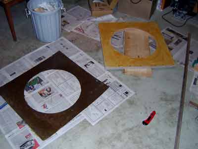
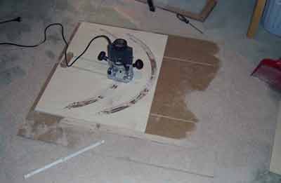
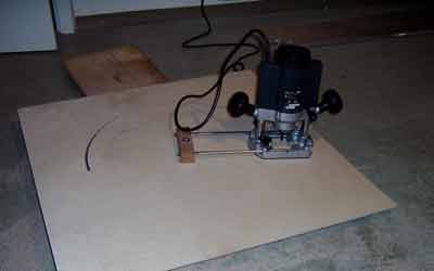
The
altitude wheels were made with a router. Routers are brute, loud, and
make a big mess. Therefore follow all safety instructions
|
|
| For the routing I prepared a 12 mm support board, where all the parts could be mounted securely. |
|
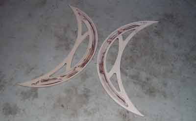
| The hollow halves of the bearings. |
 |
|
Gluing together the halves. |
|
|
Update: To facilitate transport in my car with the main bearings still attached, I combined the front parts of the crescents to a "box". This works really well and had no pronounced side effect on the stability of the Dob. The size of the bearings was furthermore somewhat increased to account for a larger weigth at the secondary cage due to heavier finder and eyepieces. Due to the generally more stable construction as compared to simple crescents, a thickness of 21mm was sufficient. The bearings are therefore not hollow, but were simply cut with the router. |
  |
|
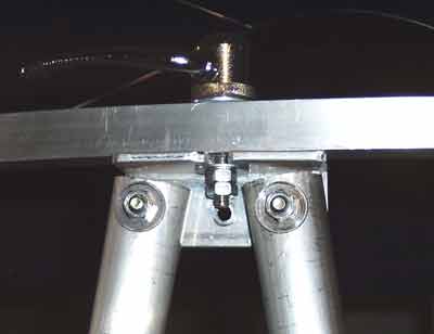
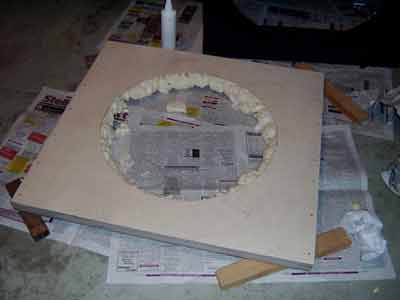
The rocker box The base of the rocker box was made as a sandwich somewhat similar to (though not as elaborate as) that of the 24" Dobsonian of Stathis Kafalis. It consists of a framework of 21 mm thick plywood between a 6.4 mm plywood board at the bottom and a 4 mm plywood board on top. |
|
| The voids were filled with PU foam and the circle was lined inside with thin plywood. |
 |
|
The bearing material of the azimuth bearing is Ebony Star on Teflon , which was cut with a knife and laminated with contact glue. For the azimuth bearing, Teflon on Ebony Star works fine (in contrast to the altitude bearings). Smooth movements, no sticking. |
|
|
The ground board ... was made of 12 mm coated plywood. There are sometimes misunderstandings regarding the rollers: the sole role of the rollers is to prevent the rocker box from sliding off the ground board. There may be some play between the rollers and the circular cutout of the rocker box, which likewise does not need to be *perfectly* round (unlike the altitude bearings). |
|
|
The EQ platform ... ... is a "must" to me. Once you have observed with a well-built platform, you would not want to go without one. The most important things about a good platform are a low profile, stiffness, and no introduction of vibrations. |
|
|
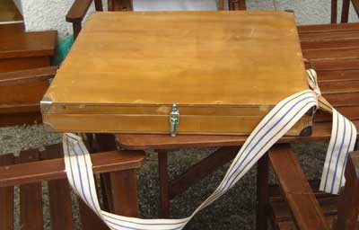
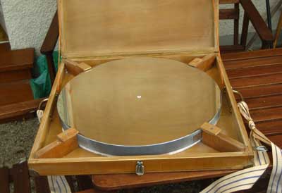
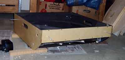
The mirror transport box ... is helpful to reduce the weight of the heaviest part, the mirror box. The transport box protects the mirror during transport and can be carried vertically. Mounting and dismounting of the mirror is a matter of half a minute and not a problem at all. |
|
|
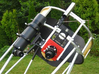
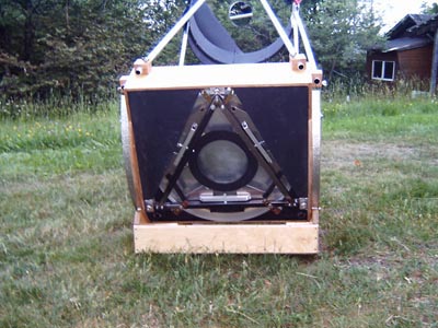
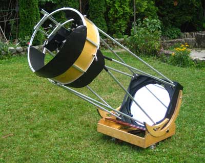
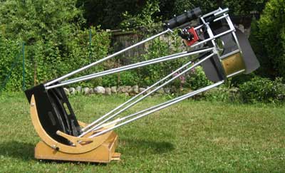
The telescope ... fully assembled on the equatorial platform.
|
|
![]()
| home | introduction | telescope | primary mirror | secondary mirror | eq platform |