equatorial platform
|
equatorial platform |
|
Dobsonians are alt-azimuthal telescopes, as everybody knows. This may be a disadvantage if you want to observe Jupiter at say 400x. It does work, of course, but it requires some practice and smooth operation of the telescope mount. Nevertheless, it would be nice, if Jupiter would just stay in the middle of your field of view.
There is a relatively simple method to realize an equatorial mount for Dobsonians, particularly if you are interested in visual use only. And the particularly nice thing is: it works equally well even for larger Dobsonians. The answer is the equatorial platform or equatorial table, which serves as a tracking platform for the Dobsonian telescope. The design of such platforms was first described by Adrien Poncet and later further pushed by Alan Gee and Georges d'Autume (see below).
|
|
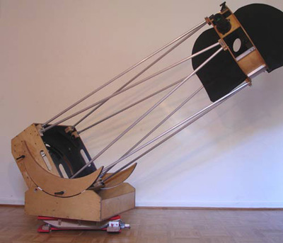
An EQ platform serves as an equatorially mounted table for the telescope, which is used instead of the ground board. The picture on the left shows my 14-Inch Dob on its platform. An EQ platform maintains the intuitively simple handling of the Dobsonian telescope. |
|
|
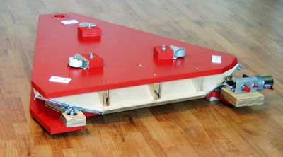
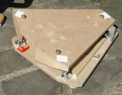
This picture shows a circle segment (CS) platform, a combination of Poncet and Gee type (see below), without the Dobsonian telescope. The platform is 9 cm high and replaces the regular 3 cm ground board of the telescope. The platform increases therefore the height of the telescope by only 6 cm. The small rollers on the platform table have no functions for the platform, but are required for guiding the rocker box of the Dob (instead of a central bolt). |
|
|
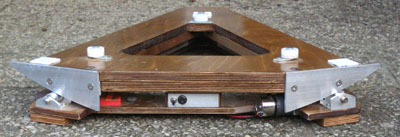
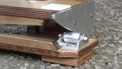
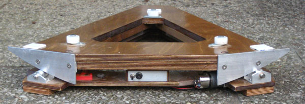
This is another platform that I built for my 22 Inch Lowrider Dob. This platform has a somewhat different design (somewhat similar to the Autume type, which will be explained in more detail further below) and can carry also heavier telescopes (>40 kg). This platform is conceptually more complex and is introduced in detail here. |
How does a platform work?
|
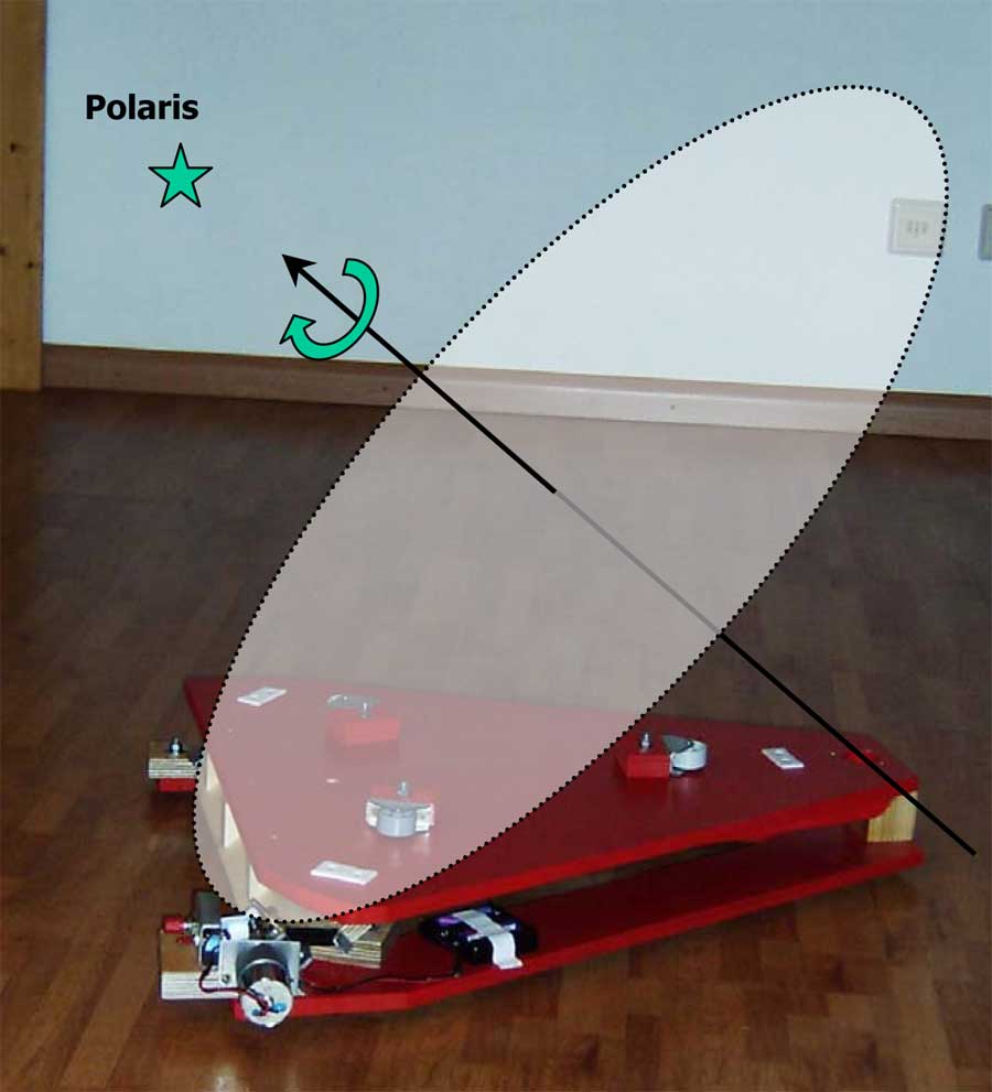
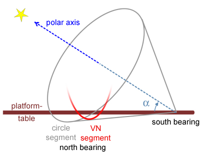
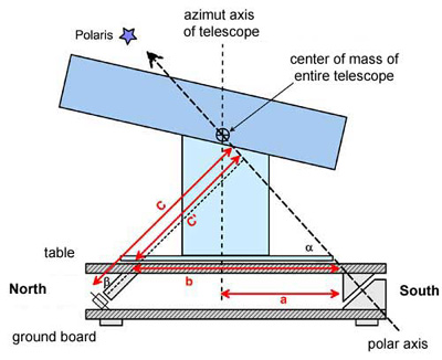
The principle behind it is simple. A platform consists of two parts, a ground board on which a pivoting table is mounted. The pivot axis is set parallel to earth's polar axis, the table is hence mounted equatorially. At 50° northern latitude, the pivot axis is inclined at an angle of 50° to the surface, pointing to Polaris. In order to serve as a sturdy basis, the table needs to be mounted at three points. The southern bearing (to the right in the picture) is easy to make. It is an axial bearing oriented along the polar axis. On the northern side (to the left in the picture) the situation is more complicated, as the axis of rotation is far away above the table. Instead of an axial bearing, a large circle perpendicular to the polar axis is used, which is riding on small inclined roller bearings on the ground board. As obvious from the picture, we do not need the entire circle for the bearing. To support tracking for one hour, only a relatively small circle segment is needed, which will be mounted underneath the platform table. The table will be turned around the polar axis by a rate of 15° per hour (360°/24h), such that one hour tracking can be realized without any risk of the telescope tipping over (actually the earth takes a few minutes less than 24 h for one rotation, but we make no major mistake by assuming 24 h). After one hour of tracking, the platform can be reset by hand into its initial position. |
|
Instead of a circle segment, any section through the cone in the scheme to the right would work. This is exploited in the VNS platforms, which will be described below and which use vertical elliptical or hyperbolic segments for the northern bearing. |
|
Different modern design variants of an equatorial platform
Besides this most simple CS platform type, where both the circle segment and its roller bearings are inclined, pointing along the polar axis, there are also other variants. Before focusing on planning and building of the platform, I would like to introduce a few of these variations.
The segment of the northern bearing can, for instance, be mount vertically (it should then be further split into two halves, which are slightly turned). For this type of platform, horizontal instead of inclined roller can be used for the bearing, which allows for a better force transmission from the table to the ground board. Planning of this type of platform is a bit more complicated, as the northern bearing is no longer a simple circle segment, but rather elliptic. Furthermore, the northern bearing segment slightly tilts during tracking, such that the bearing surface has a complex shape. For large, heavy telescopes this type of platform has, however, clear advantages.
|
How could we make these more complicated segments of the northern bearing for this type of platform? One possibility consists of making kind of a jig, by which we can rotate the platform table exactly as later in the finished platform and move the bearing surfaces along a router. This approach is introduced on the website of Ulli Vedder, who has used it to build the platform shown to the right, and on this website. |
|
|
Alternatively, the precise shape of the segments of the northern bearing can be calculated and templates can be made by using a drawing program. If the segments are thin, the tilt movement of the segments during tracking can be neglected. How to calculate the shape of the elliptical segments and how to make them is shown on the web page of the platform of my 22-Inch Lowrider Dob. |
|
|
Another design variant consists of using an inclined northern bearing segment, and sloping the bearing surface instead, such that the rollers supporting the segment can be mounted horizontally. This variant combines many advantages and should be well suited also for heavier Dobs. A very well executed example of this type of platform was made by Ed Jones and is shown to the right. This platform is very well crafted and has a very elegant look. Reading Ed's report should be a MUST for every potential platform builder! |
|
|
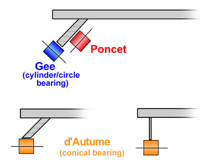
"Historical" development of design variants Adrien Poncet described his type of equatorial platform in 1977 using simply a plane perpendicular to the polar axis as a bearing surface. The shape of this bearing surface was not important, solely its right angle to the polar axis. This surface was supported by inclined rollers. This type of platform works well for high latitudes, where the inclination of this plane is low. At lower latitudes, however, the inclination of this plane increases and the load distribution becomes very unfavorable. Alan Gee altered this design by giving this bearing surface an explicit circle shape (cylindrical bearing). This circle is then supported (again by inclined rollers) via the edge. While this type works now well for low latitudes, it is not as well suited for higher latitudes. Modern platforms with circle (or cylinder) bearings are usually combinations of both Poncet and Gee type and use roller support both via the edge and the surface of the circle segment. Georges d'Autume finally suggested 1988 to use a cone as a general bearing surface (conical bearing, see picture above). This allows the usage of horizontal instead of inclined rollers. The VNS platform as well as Ed Jones' platform (see pictures above) are variants of this d'Autume type. |
|
The platform in practice
How does an EQ platform perform in practice? As the allowances for tracking inaccuracies are several orders of magnitude higher for visual observing as compared with photography, also the allowances for small errors during building or aligning the platform are higher than one might expect. As a general practice, I align my platform only roughly, using either Polaris or a small compass. I found this rough alignment to be sufficient for visual observing.
During "first light" of my platform I was, of course, excited. I set up the platform and aligned it and put the telescope on top of it. Then I pointed the telescope to a star close to the equator and magnified to almost 900x. And the star ... it just stayed there in the middle of the field of view.
A platform is helpful not only for observing planets or the moon. It is also helpful for Deep Sky work, where high magnification can be used as well, e.g. for splitting close galaxy groups or for observing small planetaries. It is also very convenient, if you can leave the telescope for an instance to have a look at the star atlas or a guide book without loosing your object. And finally, a platform is particularly useful, if you want to show an object to other observers.
Designing the platform
... is described in detail here.
... and ready-to-use designs of some platforms are here.
Careful
planning is quite important for designing a successful
 platform.
First,
one should really understand, how a platform works in detail. Otherwise, it will
be hopeless ...
![]() .
.
It is important to design a platform that fits your telescope. Therefore, I do not post here finished construction plans of my platform, as this one was specifically designed for my 14" truss tube Dob. A platform for a commercial 8 to 12 inch solid tube Dob will necessarily have different dimensions. How to determine the dimensions of a platform specific for your own telescope will be explained in detail here.
First you should specify the geographic latitude alpha for which you would like to design your platform. The latitude determines the inclination of the polar axis to the earth's surface, which is, of course, the same angle a between the polar axis and the platform. Second, you determine the height of the center of mass (CM) of the telescope (OTA and rocker box). In order to enable a platform operating free of torque, it makes sense to design the platform such that the CM of the telescope coincides with the polar axis (see figure to the side). You can determine the height of the CM of the entire telescope from the height of the CMs of the tube and the rocker box: (height of the CM of the tube x mass of the tube + height of the CM of the rocker box x mass of the rocker box) / total mass.
Generally, I want to encourage everybody to take a look at all the other platforms in the link list below. Every platform features different ideas due to different expectations and capabilities of the person behind it. The way I built my platform represents only one possibility among many others, and I am sure there would be a good number of observers who would not be content with such a platform, and this for right.
EQ platform link list at Stellafane
VNS (Vertical North Segments) platforms
My own VNS platforms for 14" and 22" Dobs with direct drive
Tom Osypowski (Equatorial Platforms) (commercially available VNS platforms with direct drive in either wood or alloy, with alt-drive)
Daniel Restemeier (VNS platform for 16" Dob)
Martin Brückner (VNS platform for 18" Dob)
Uwe Glahn (super solid VNS aluminum platform for 27" Dob)
Platforms with circle segments
Ed Jones (a great platform with a simple, yet very elegant design, combining the advantages of conical and cylindrical bearing, it's marvelous!)
Christof Gurdan (platform with uncomplicated gear wheel drive)
Jens Decker (platform for 18" Dob, beveled north bearings à la Ed Jones)
André Heijkoop (platform for 14" with friction drive)
Drive systems
Viktor Schmidt (Ascom Driver for Arduino Nano and stepper motor)
Manufacturers of platforms
Tom Osypowski (Equatorial Platforms), rock solid VNS platforms with direct drive in wood or aluminum by the EQ platform pioneer, USA
AstroThingy Aluminum platforms by Harry Feigel
Pierre Desvaux (Dobson Factory), beautifully handcrafted (quite expensive) platforms from France
![]()
home introduction cs platform vns platform drive system planning construction plan