planning an equatorial
platform
On
this page, I would like to give a step-by-step approach for designing an
equatorial platform. These steps are initially the same whether you want to
build a circle segment platform or a VNS platform. Complete
ready-to-use designs of platforms for 8" to 10" Dobsonians are
here.
|
 |
Choice
of platform type |
|
|
Determining
the center of gravity of telescope and platform table |
|
|
Graphical
determination of the length of the platform |
|
|
Graphical
determination of the width of the platform and of the radius of
the circle segment |
|
|
Transformation
of the circle segment into VNS segments |
Choice
of the platform type
As
a first step, we need to decide which type of platform we would like to build.
|
The
platform type that is the easiest to understand is the circle segment (CS)
platform with a tilted circle segment as northern bearing. This platform
type has several disadvantages and does not allow in particular for a true
three-point support. |
|
|
Somewhat
more complex are the VNS platforms with vertical north segments. The offer
a number of advantages, such as an easier construction of the roller
bearings, a more direct weight transmission, a true three-point support,
and a higher load capacity. |
 |
|
A
further option addresses the way the Dobsonian telescope is mounted on the
platform.
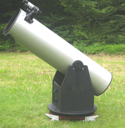
You
may put your Dob together with its ground board onto the platform. In
this case it is useful to add fixtures on the platform table that keep
the feet of the Dob's ground board in place.
This
options is particularly useful for smaller Dobsonians, for which the
additional increase of eyepiece height by the ground board does not
matter. Furthermore, the ground board remains an integral part of the Dob, which can be used with or without platform without the need to
mount or dismount anything.
|
|
|
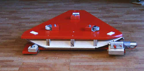
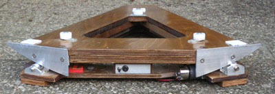
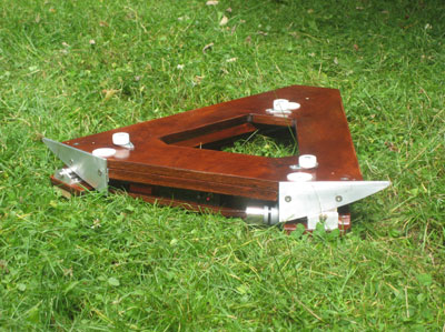
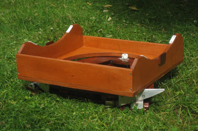
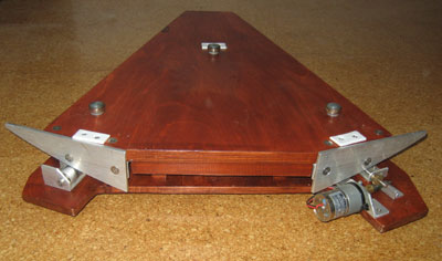
For
larger Dobsonian telescopes, the eyepiece height is an issue. Therefore it is
useful to save the height of the ground board and let the platform table
take over its role. In this case the guiding rollers that hold the rocker
box (for rocker boxes with round cut-outs at the bottom) or the central
bolt (for rocker boxes with conventional azimuth bearings) can be attached
to the platform table together with the Teflon pads. In the latter case
(rocker boxes with traditional central bolt) you may not cut out the
center of the platform table. Due to its easier mounting and dismounting,
a rocker box design with cut-out bottom as in the picture to the right is
of advantage. |
 |
Determining
the center of gravity of the telescope and the platform table
As
the first step in designing the platform, we select a reference plane. For a
circle segment platform, where the northern segment is mounted under the
platform table, the bottom side of the platform table is a suitable reference
plane. For a VNS platform where the upper edge of the segments are in line with
the upper side of the platform table, this upper side is the best choice as
reference plane. In the following, we will take this upper side of the platform
table as reference plane.
As
a second step, we need to determine the center of gravity of the system of parts
that are moved by the platform. This includes the telescope optical tube, the
rocker box (+ eventually the ground board), and the platform table.
Graphical
determination of the length of the platform
|
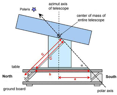
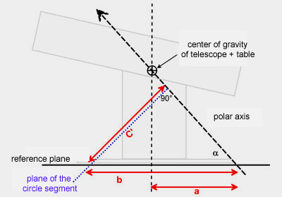
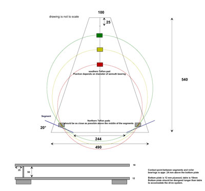
In
the cartoon to the right, the most important measures of the platform and
the telescope are summarized. In the following we will learn step by step,
how to calculate these measures. As mentioned above, we will take the
upper side of the platform table as reference plane. The angle alpha
corresponds to the geographic latitude, the angle beta is 90° -
alpha. |
 |
|
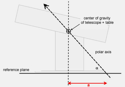
As
a first step, we draw the reference plane and the polar axis
in an angle alpha corresponding to your latitude. To support the telescope
in its center of gravity, this center of gravity needs to be on the polar
axis (= axis of rotation). This determines the distance a between
the intersection of the azimuth axis and the polar axis with the reference
plane. |
 |
|
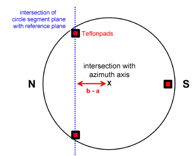
In
a next step, we will switch into the reference plane. We draw a circle
around the intersection point with the azimuth axis corresponding to the
size of the azimuth bearing surface (e.g. the ebony star ring under the
rocker box), such that the Teflon pads (or alternatively the feet of the
ground board, if this will be used on the platform) are just within this
circumference. One of the Teflon pads points toward south, while the
positions of the other two will define the intersection line of the future
circle segment with the reference plane. From the drawing, you can further
determine the distance b - a. |
 |
|
Now,
we switch back into the side perspective. The distance b is now
defined. Next, we will draw the plane of the future circle segment, which
is perpendicular to the polar axis. The distance between polar axis and
intersection with the reference plane is c'.
|
 |
Graphical determination of the
width of the platform and of the radius of the circle segment
|
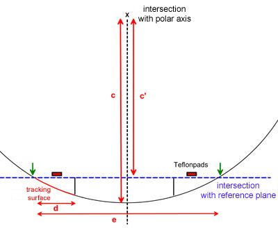
In
the next step we switch into the plane of the circle segment. We draw the
intersection of the polar axis (= center of the future circle segment) and
in a distance c' the intersection of the circle segment plane with
the plane of reference.
We
can now place the two northern Teflon pads along this intersection line.
The future circle segment (and thus the width of the platform) should be
somewhat wider than the distance between the Teflon pads (in practice
about 10 cm on each side, half of the length of the tracking surfaces).
For 1 1/2 hours of tracking, the length of the tracking surface
(corresponding approximately to d) is
(1.5h/24h)
x 2 c pi
With
a pair of compasses we can now draw the circle segment between the two
green arrows and determine its radius c as well as the width of the
platform e.
For
Dobs with relatively small ground board and/or high center of gravity,
this method would lead to a narrow, long platform. In this case, it may be
useful to make the circle segment somewhat wider. The Teflon pads will
then be no longer in the middle of the tracking surfaces, but are shifted
toward their inner ends. |
 |
Now
we have determined all the measures for a platform with circle segment.
It
is generally easier to make a platform for a broad Dob with low center of
gravity than for a tall Dobson with small ground board. In the latter case one
may need to make a compromise (as shown above) and possibly also abandon the
idea of supporting the Dobson in its center of gravity to some extent.
Alternatively, one may also elevate the southern bearing, as shown here
and here,
or use a circle segment bearing as well for the southern bearing, such as here
or here. This
might be necessary in general for platforms built for more southern
latitudes.
In
any case, the circle segment can and should be mounted such that the two
northern Teflon bearings are as directly as possibly above the northern
bearings. This is very important for the stability of the platform.
Transformation
of the circle segment into VNS segments
|
For
a VNS platform, we still need to make the transformation from the circle
segment to the elliptical VNS segments. This will be achieved in two
steps.
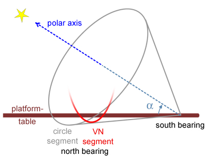
As explained already
here, the usual circular
segment for the northern bearing is only a special case of a continuum of
possible shapes, which all are sections of a cone. This cone is defined by
the polar axis and an angle, which is slightly larger than the
geographical latitude (otherwise the segment would not be below the
horizontal table). For a circular segment, the plane of the section is
perpendicular to the polar axis. In our alternative approach, we can put
the plane of the section perpendicular to the platform table. What we get
is an ellipse or an elliptical or hyperbolic segment (see conic
sections on Wikipedia).
The advantage of
vertical northern segments (VNS) is the more direct transmission of the
weight of the Dob to the ground plate and the simpler design of the
roller bearings and the motor drive. |
 |
|
The shape of the VNS segments can be calculated and drawn to scale. This can be
done analytically, but this is complicated. It is much more simple to start from
the inclined circular segment. The shape of the
vertical elliptical segment is obtained by a simple projection of the inclined
circle segment into a vertical plane, followed by dividing of the segment
into two parts and a slight rotation of each of the parts around a
vertical axis.
By the projection
into the vertical plane, the circle is compressed by a factor of cos
alpha
(where alpha
is again the geographical latitude). The circle segment turns to an elliptical
segment. This procedure is best done using some simple graphic software,
from which you can print out the part of the segment that you need (even
Powerpoint could do this). It is helpful to draw also the position of the
reference plane (the horizontal line in the scheme) and the area needed
for the tracking surfaces (marked by vertical lines).
|
|
|
In the next step, the
elliptical segment are split into two segments, that are slightly rotated by an angle beta around a vertical axis
such that they are perpendicular to the line connecting them with the
southern bearing. This will align the segments with the movement of the platform
table and decreases the amount of lateral movement of the segment on the
rollers during operation of the platform. To account for this, the
segments need to be stretched by a factor 1/ cos beta. The
segment (only that part that is needed) can then be printed on a sheet of
paper and serve as a jig for cutting out the segments. In
contrast to the circle segment, the points on the tracking surface of a
VNS segment do not maintain precisely the same distance to the southern
pivot point. With some brainstorming, one can deduce that the required
tracking speed is no longer constant but becomes a function of the
position of the tracking surface. One can, however, determine the
deviation from an average tracking speed, which is less than +/- 1%. |
|
Complete
Designs of VNS platforms for 8 and 10" Dobs
|
Here are complete designs
for the common 8 to 10" Dobs, together with all required dimensions and
templates for the VNS segments for 46 to 52° latitude. |
 |

home
introduction
cs platform
vns platform
drive system
planning
construction plan
