circle segment platform
|
circle segment platform |
|
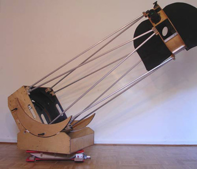
The platform shown here was designed to be as simple as possibly with little expenses for material or cost. It is well suited for starting a platform project, during which you may develop your own ideas about how to make *your* platform. This platform uses a circular northern bearing and is often termed Cylindrical Bearing Platform. It has a very simple capstan drive, which is easy to make and which can be powered by a simple geared DC motor without any electronic control. I often make the experience that people are hesitating to make a platform as they are afraid of fancy electronics needed to control the tracking. The concept shown here certainly imposes no major difficulties. It can easily be improved by using more advanced voltage controls (as shown here) or by using a stepper motor setup, which, of course, requires also a considerably more extensive power supply.
|
|
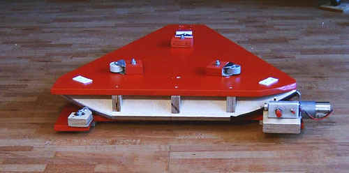
This picture shows the platform with a 14" Dobsonian telescope. The platform is 9 cm high and replaces the regular 3 cm ground board of the telescope. The platform increases therefore the height of the telescope by only 6 cm. |
Designing the platform
... is described in detail here.
Making of a simple CS platform
|
|
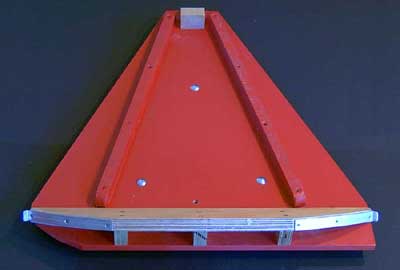
The upper table and the ground board consist of 10 mm varnished hardboard (plywood is certainly better), the table being additionally reinforced. The northern roller bearings consist of furniture rollers, which are screwed onto small plywood boards that can be adjusted on the ground board (6 mm bolts in 15 mm drilling holes). The rollers can therefore be adjusted to the bearing segments and are then fixed by tightening the bolts. The circle segment is made of 21 mm plywood and is best made with a a router. It can also be made with a jig saw if care is taken that the cut is perpendicular to the surface.
|
|
The southern bearing consists of a machine bolt and a plastic washer between two steel washers. Note that the Teflon pad of the azimuth bearing is not directly above the southern bearing of the platform. As the platform table has been additionally reinforced, this does not impose a major problem. |
|
|
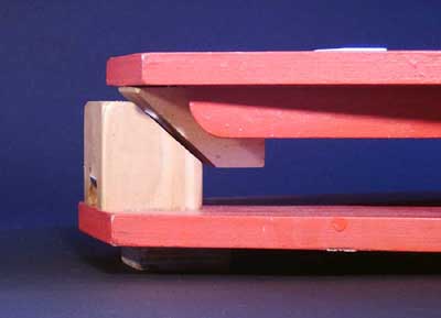
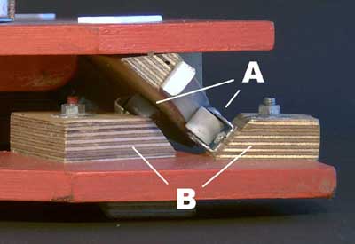
One of the northern bearings. The circular segments are long enough to allow for about one hour of guiding. The bearings to the left supports the inclined segment from the back, thereby decreasing the load on the single bearings. Here, the Teflon pad of the azimuth bearing is directly above the platform bearing. |
|
|
|
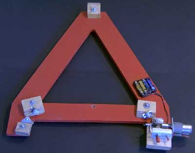
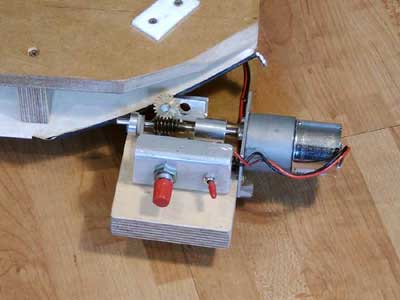
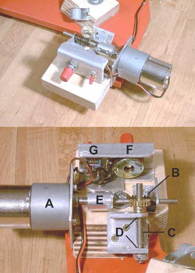
I did not want to use a spindle drive/tangential arm but rather a capstan drive, which is easier to make and which can be reset by simply lifting the platform table. The segment of the northern bearing is resting directly on a steel capstan. As the friction between alloy and steel was not sufficient, I pulled a piece of resistant rubber tubing on the steel axis, which has good grip on the alloy of the segment. A rubber roll would even perform better. The capstan is mounted in small ball bearings. The radius of the northern bearing full circle is 445 mm, its perimeter therefore roughly 2800 mm. As it has to turn once in 24h, we can calculate a speed of about 2 mm per minute for accurate tracking. The platform is powered by a RB35 geared DC Motor (1:600) and a 1:20 worm drive. Power supply is from a 6 V battery pack (4x AA), a switch, and a potentiometer to adjust the motor speed. More information on the motor and its control can be found here. The capstan has a diameter of 6.5 mm and hence a perimeter of about 20 mm. I has to turn with 0.1 rpm. With the 1:20 worm drive, this corresponds to about 2 rpm of the geared motor. This is achieved at a voltage of roughly 3 V, which can be adjusted by the potentiometer (using a 100 Ohm potentiometer, you have enough margin to adjust the voltage for precise tracking). In the table to the right, the RP35 1:600 motor speed is given as a function of voltage (note that this is only approximate and may vary for individual motors). In the lower picture, the driving unit is shown in more detail, with the geared motor (A), the worm drive (B), and the cabstand with the rubber tubing (C) in the ball bearings (D). There is further an adapter (E) to connect the worm drive to the motor, the switch (G) and the potentiometer (F). |
![]()
home introduction cs platform vns platform drive system planning construction plan